
Designing for sheet metal fabrication is not merely a matter of drawing functional forms on a screen. It is an exercise in understanding transformation – how flat, cold sheet stock becomes a sturdy, reliable component. Every curve, cut, and corner must be designed to work with, not against, the realities of fabrication.
For engineers, manufacturers, and product designers alike, the stakes are high. An effective sheet metal design can spell the difference between seamless production and a bottlenecked nightmare of delays, scrap, and spiraling costs. In today’s manufacturing environment, there is little margin for error and even less patience for costly rework.
Let’s walk through the essential design practices that help avoid bottlenecks, rework, or delay designing sheet metal parts.
Sheet Metal General Design Considerations
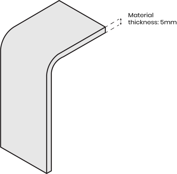
Maintain uniform wall thickness:
Ensure uniform wall thickness to avoid abrupt thickness transitions. This helps in consistent bending and cutting. We recommend sheet metal thickness between 0.5–10 mm for laser cutting, and 0.5–6 mm for bending.
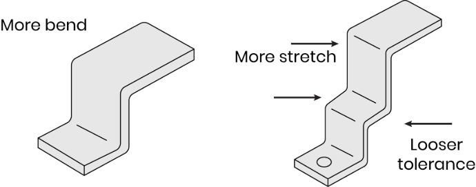
Allow realistic tolerances
Since sheet metal fabrication stretches during bending, tolerances are usually more relaxed than in CNC machining. Setting extremely tight tolerances will complicate fabrication and increase cost.
Design Best Practices for Laser Cutting
Add fillets to the corners
Sheet metal part corners are extremely sharp, by using fillets that are half the material thickness makes the part safer and avoids cuts during handling the parts.
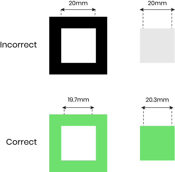
Consider the Kerf
A small amount of part is removed during laser cutting, typically around 0.3 mm. To make the parts properly fit when assembled, split the kerf between the inner and outer parts to maintain accurate fits.
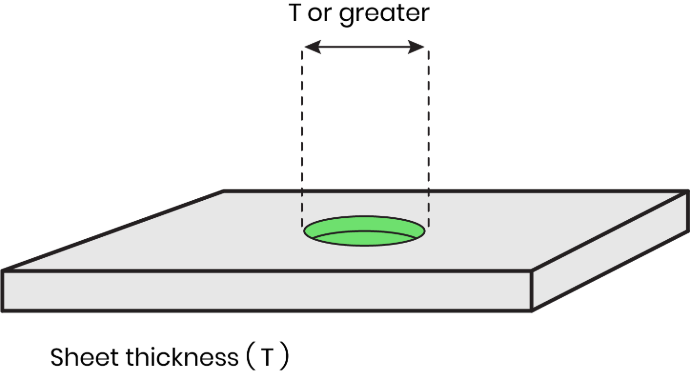
Design holes at least equal to the material thickness
To prevent deformation and inaccuracies during cutting, the hole should be designed with a diameter equal to or larger than the sheet thickness.
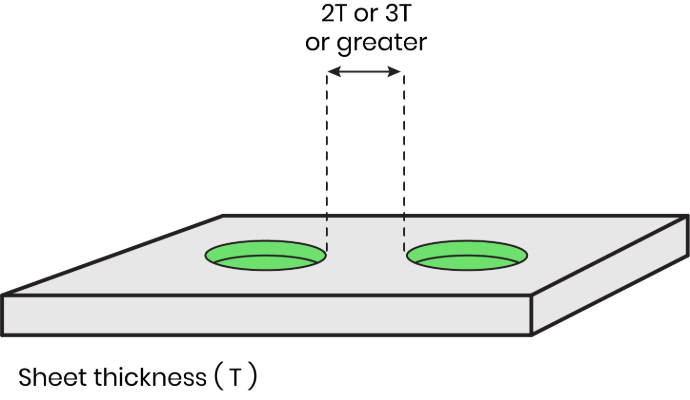
Space holes at least 2× the material thickness apart
Holes that are too close to each other can weaken the part or deform during forming, so keep the holes spaced at least twice the material thickness.
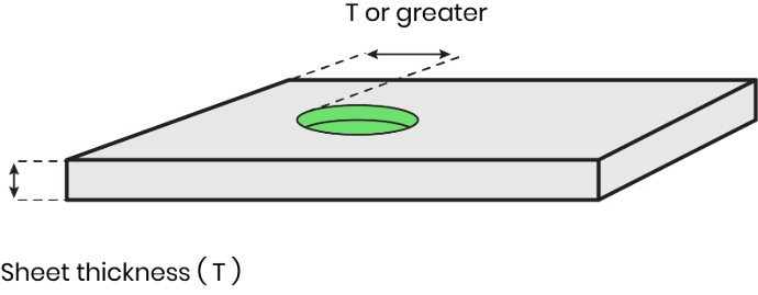
Keep holes at least 1× the material thickness from the sheet edge
If holes are placed on the edge of the sheet, the risk of holes tearing or edge distortion is higher during fabrication. Keep holes at least one material thickness away from the sheet edge to reduce the risk.
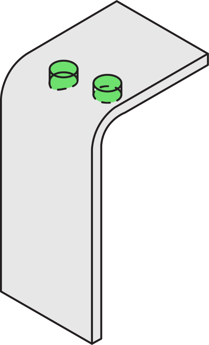
Avoid placing holes too close to bend lines
Holes too close to bends may get distorted or act unintentionally as relief cuts. Position the hole two times the material thickness away from the start of any bend radius.
Design Best Practices for Bending
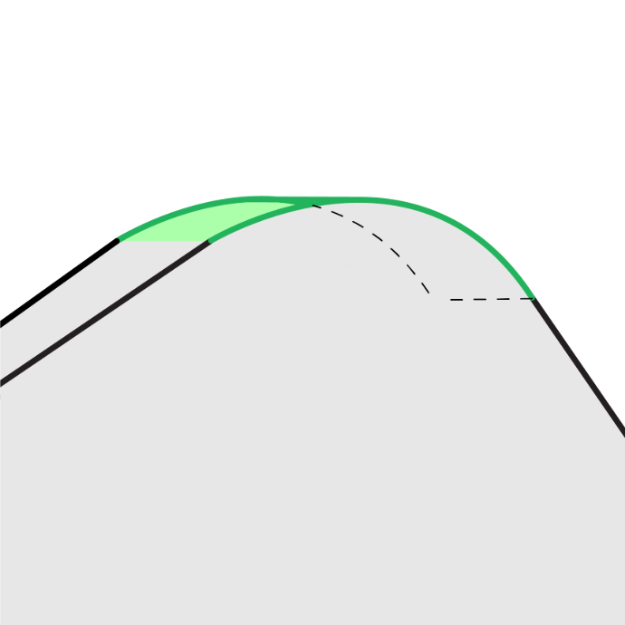
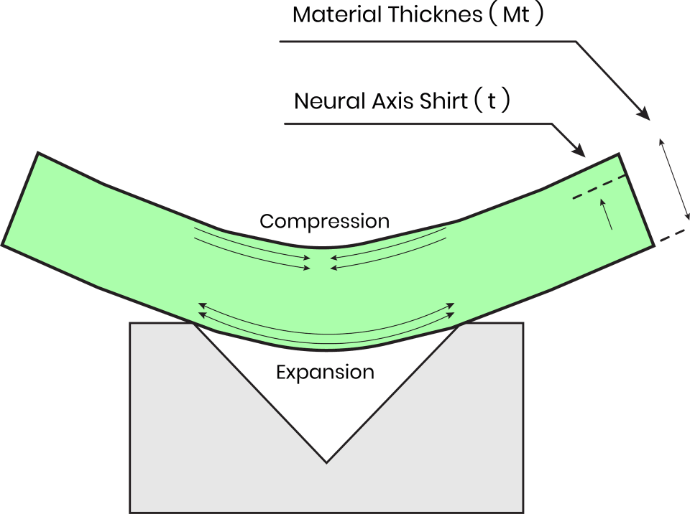
Use the K-Factor
While bending the sheet metal, the material naturally stretches during the process. To predict how the metal will behave, use the K factor.
K factor represents a ratio of the neutral axis to the material thickness.
K-factor - t/ Mt
The value of the k factor depends on the material, thickness, bend radius, and bending method. Typically, the k factor ranges between 0.3 to 0.5 mm
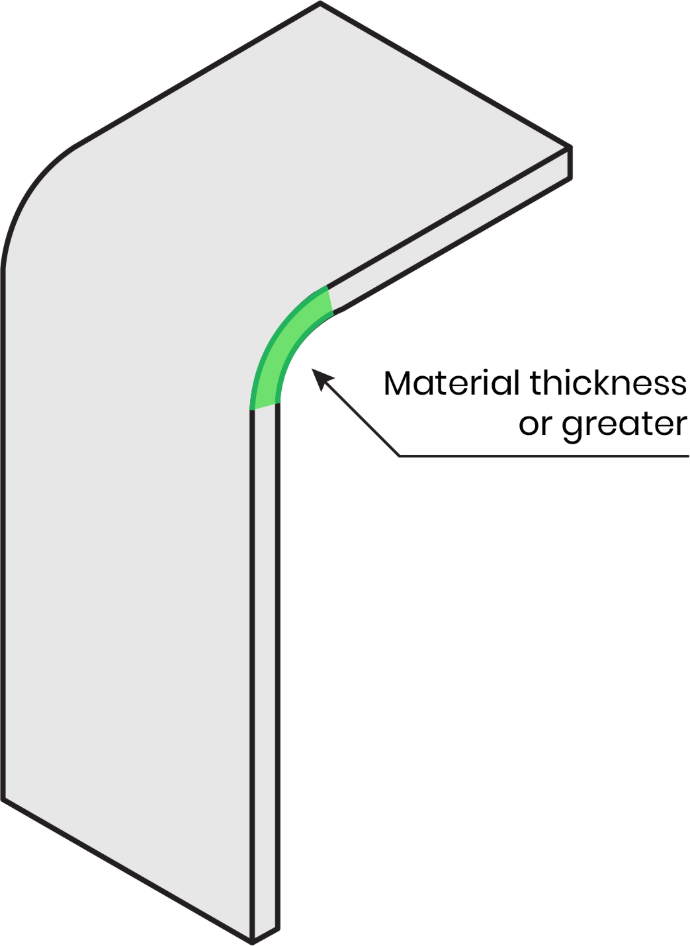
Set internal bend radius ≥ material thickness
It is nearly impossible to create a sharp corner while bending sheet metal. Setting the internal bend radius to be equal to or greater than the material thickness helps maintain the part's structural integrity and prevent cracking during bending.
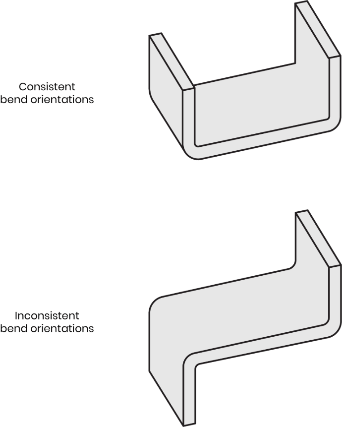
Use consistent bend radii and orientations
Maintaining consistent bend radii and orientations throughout the design reduces frequent reorienting during fabrication, consuming both time and cost.
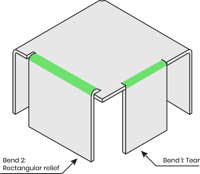
Add bend relief cuts
Bend reliefs are the small cuts placed near the bend area. Add bend relief cuts to prevent cracks, tear and unwanted bends. These cuts reduce the stress on the metal and help it to return to its shape more easily. To get the best results, make sure the relief cut is at least as wide as the thickness of the sheet metal.
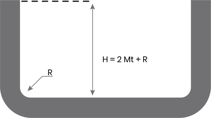
Keep bend height ≥ 2× material thickness + bend radius
Ensure that your bend height is at least double the material thickness plus the bend radius. Shorter bend heights are difficult to form and deform under pressure during press brake operations.
These rules will help designers produce precisely, reasonably priced, fabrication-ready sheet metal components.
Conclusion
Sheet metal manufacturing is not simply about engineering; it's about anticipation. Anticipating how metal moves, how machines respond, and how errors creep in when theory diverges from practice.
The most effective designers ask one key question early and often: “How will this be made?”
Those who do invariably produce designs that are easier to fabricate, more reliable in operation, and more cost-efficient in production. It’s not about limiting innovation. It’s about designing with intent.
Ready to Build Smarter?
If you're seeking a fabrication partner that goes beyond the blueprint, consider Mech Power. We don't just execute designs; we refine them. From prototype to production, our approach is consultative, collaborative, and built around quality at every stage.
Whether you're developing your first sheet metal part or refining an existing assembly, we’re here to help you design smarter, fabricate faster, and deliver better.
Talk to Mech Power today at [email protected] or +91 9898412126
Let’s turn great ideas into exceptional sheet metal parts.